This type of camera is used in IEE. Thus, you should read over the
information provided (including some great pictures) in this freshman
course, much of which addresses the safety issues you will encounter.
This information can be found at http://hibp.ecse.rpi.edu/%7Econnor/education/IEE/lectures/Lecture_9_flash_camera.pdf
and http://hibp.ecse.rpi.edu/%7Econnor/education/IEE/IEE-Lec9.ppt.
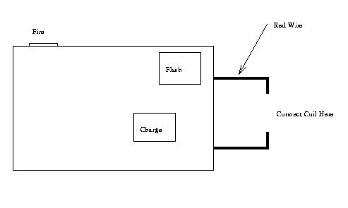
You are to design and build a coil that
is connected to the wire that leads to the flash tube in the camera.
You must demonstrate how far your coil can launch the piece of a paper
clip. The number of bonus points you get will depend on the number of
feet the projectile travels. At present, one point is earned for each
foot in excess of 20 that the projectile travels horizontally. (Note that there may be a maximum number of extra credit points allowed in the course.) The
launcher must be placed on the floor and the floor must be carpeted.
Usually measurements are made outside of Prof. Connor's office or in JEC 4107. You
must obtain the camera from Professor Connor, Professor Schoch or one
of the instructors from your course. You have learned in this or a
previous class that a transformer can be used step up a small AC
signal to a larger value, or vice-versa. The Flash
camera uses this property to create a large rectified AC signal to
charge a
capacitor to about 320 volts. The small AC signal is created by a
simple oscillator circuit (this is the whining noise you hear while the
flash is charging). The energy stored in the capacitor is used to
ionize the gas in
the Xenon flash. Xenon is normally a good insulator, however when it
triggered by a very low energy, high voltage pulse, a small number of
free electrons are created that can carry a current and it starts to
become more of a
conductor. Once it begins to conduct, the charge from the capacitor
begins to flow through the ionized Xenon, which creates even more free
electrons. This avalanche effect eventually brings
the resistance down so low (to around 1 ohm) that the large capacitor
that was charged to 320V will rapidly discharge itself through the
Xenon tube. After all the current has
dissipated, the Xenon gas acts like an insulator again and the process
can
start over again. WARNING:
Typical capacitors in disposable camera flashes charge to over 300
Volts and have a capacitance in excess of 100uF. In this case, 320
DC volts will not kill you, but it will hurt if it
burns you. What makes this circuit safer than others is that
the two capacitor contacts are close together and, thus, you are not
likely to grab them separately with two hands. You always want to be
sure that you only use one hand when working with high or higher
voltages. To avoid having to touch the charged up capactior, solder the
circuit without the battery in place. Fully test the integrity of your
circuit before installing the battery. Make sure your solder contacts
are good both electrically and mechanically. If they are electrically
poor, they are likely to blow up as the current from the capacitor
heats the highly resistive poor connection. If they are bad
mechanically, they may break. In either case you may end up with a
fully or mostly charged battery with no simple way to discharge it,
except by hand. Remember to
discharge the circuit (generally it is a good idea to have the TA or
instructor show you how) before asking for help or trying to fix the
connections yourself. (More comments on this follow.) Try to leave as
much of the case as possible in place to cover the high voltage
connections. You can also prevent accidental pain by insulating the
camera
with electrical tape after you do your soldering.
For an easier to read diagram, check out the Postscript version.
There are a few key things to keep in mind when doing this project.
To create the coil, wind several hundred turns of #28 or similar wire around a
small plastic tube. You can get such a tube by cutting off the unused
1.5 inch section at the end of a ball point pen cartridge. The wire
should be standard magnet wire which is insulated with enamel. You will
have to remove the enamel from the ends of the wire to make a good
connection. The coil is connected in series with the flash tube. The
easiest flash tube wire to cut is the red wire (there are usually three
wires to the tube -- red, black and white -- however, sometimes they
are other colors or have no insulation at all). The red and black wires
carry the large current that we wish to divert through the coil. Make
sure your solder connections are good or the high current will blow
them apart. If the wires are disconnected and the capacitor is charged
up, you have a safety problem You will have to use a screwdriver to
short out the capacitor so you do not harm yourself when you try to
resolder the wires. Wear safety glasses when you do this since you are
likely to create sparks. Once you have the coil connected properly, you
should fix it to a piece of cardboard or to the camera body. Both work
fine.
To operate the launcher, you must first cock the shutter. Look at the picture of the cheesey launcher. The small white lever located on the front of the camera just below the shutter must be moved until you hear a click. Try the shutter to be sure you are doing the right thing. (Do this before you install the battery.) If the white lever moves when you push the shutter button, you are ok. Cock the shutter again. You charge the capacitor by pushing the charge button, which is located on the front of the camera below the flash. Hold this button in until the small neon bulb (usually located on the top of the camera, but not always) flashes vigorously. The flash will fire anytime after the bulb lights, but a bit more charge will help the projectile fly further. Hold the camera and coil in front of you. Place a small straight piece of a paper clip (about 1 cm long) in the end of the coil nearest you. Leave a little bit of the paper clip piece showing. Once the coil is energized, the clip will be pulled into the coil and proceed out the other end. If you place the paper clip piece in the other end of the coil, it will shoot toward you. The piece of the paper clip should be as fat as possible. Use the largest diameter piece that you can find that slides easily through your plastic tube.
Finally -- push the shutter button to launch the projectile, but Please Do Not Shoot Your Eye Out!! Everyone who does this experiment should be required to watch The Christmas Story, even though the clip piece carries very little momentum and thus can do little damage. However, with a bit of work and a much larger camera flash unit (which cost a lot more), it is possible to get a piece of a nail to stick in an apple (sorry William Tell)!
Report -- you should write a short report explaining how your launcher works and any ideas you developed to improve it. You should also include a circuit diagram with the capacitor, the resistance of the flash, and the resistance and inductance of the coil. Your expression for the inductance of the coil should show how it changes as the paperclip moves through it. You can use the impedance bridge in 4107 to measure the inductance.
A general reference: http://www.coilgun.info/home.htm