The unusual selectivity of this radio is due to its special double-tuned circuit. A pair of diodes connected as a voltage-doubler provides the extra kick to operate the small speaker. An output jack is provided for headphone listening and for connecting the set to an amplifier.
Construction. The model was built on a 2 1/2" x 4 1/2" wooden chassis with a 3 1/2" x 4 1/2" metal front panel. However, size is not critical, and other materials may be substituted if desired.
Two standard ferrite loopsticks, L2 and L3, are used. Both must be modified by the addition of a second winding, L1 and L4, respectivly. Each of the added windings consists of 22 turns of No. 24 cotton-covered wire wound on a small cardboard tube as shown on the pictorial. (Actually, any wire from No. 22 to No. 28 with cotton or enamel insulation will do the job.) The diameter of the cardboard tube should be slightly larger than L2 and L3 so that L1 and L4 will slide over L2 and L3 easily.
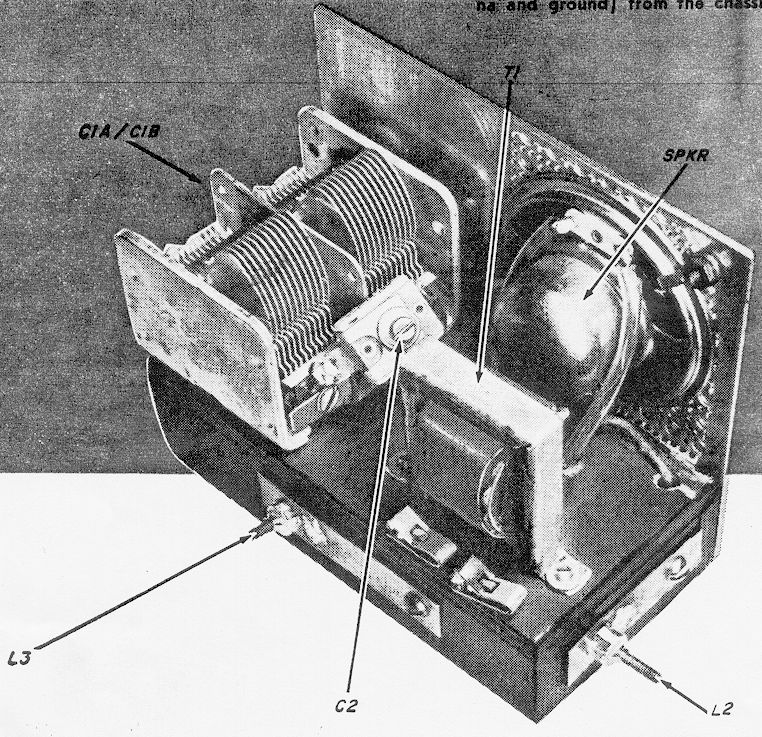
Resistor R1 is used only for feeding the set into an amplifier; it should be omitted for both earphone and loudspeaker operation. Trimmer capacitor C2 should be soldered across the stator terminals of two-gang variable capacitor C1a/C1b, as shown. The speaker and output transformer can be mounted wherever convenient.
After all the parts have been mounted on the chassis, wire them together following the the schematic and pictorial diagrams. Be sure that the diodes D1 and D2 and capacitors C3 and C4 are correctly polarized.
Alignment and Operation. To align the receiver, first connect it to an antenna and ground. (The optimum length of the antenna varies with location, but 50 feet will usually be suitable in areas serviced by several broadcast stations.) Next, plug in a high-impedence earphone at jack J1. Tune in a station near the high-frequency end of the broadcast band--say 1500kc.--and adjust the trimmer capacitors on variable capacitor C1a/C1b for the loudest signal.
Trimmer capacitor C2 should then be adjusted for the best selectivity and volume over the entire broadcast band. Finally, coils L1 and L4 can be optimumly positioned by sliding them back and forth over coils L2 and L3. If a nearby station interferes with the reception of a weaker one, tune the slug on L2 for minimum interference.
For loudspeaker operation, simply unplug the earphone from J1-- strong local stations should come in with fair volume. To operate the set as an AM tuner, wire R1 in place and connect J1 to crystal-phono input of a preamplifier or integrated amplifier. The set should give excellent results with a quality hi-fi system. -[30]-
The receiver employs a double-tuned circuit feeding a crystal-diode voltage-doubler/detector which drives a small speaker. In operation, r.f. signals picked up by the antenna system are induced into coil L2 from the coil L1. The desired signsl is selected by tuned circuit C1a-L2 and coupled through capacitor C2 to a second tuned circuit C1b-L3, which improves the selectivity by narrowing the r.f. bandpass. The twice-tuned r.f. signal is then induced into coil L4 from coil L3.
The positive half of the r.f. signal appearing across L4 passes through the diode D2 to charge the capacitor C4; the negitive half of the signal passes through the diode D1 to charge capacitor C3. Polarities of the charges on C3 and C4 are such that the effective voltage is doubled. This voltage appears across the primary of output transformer T1, which changes the high impedence at the output of diodes D1 and D2 to the low impedence required by the speaker.
When the high-impedence earphones are plugged into closed circuit jack J1, the speaker is disconnected and the output from the diodes feeds directly into the earphones. Optional load resistor R1 is placed across the output of the diodes when the receiver is used with an amplifier.
Variations on a theme: If you're so inclined to, I would install R1 inside the shell of the phone plug going to the amp, negating the need for its occasional removal from the radio circuit.Air variables seem to be scarcer than hen's teeth, and ganged ones, more so. With that in mind, somewhere I have a similar schematic that does the same thing but independently tunes L2/L3. The advantage is the ability to sharply null out an intefering signal.
Keep in mind the best laid plans..vs. Reality. Well, you know how that works. This version won't be appearing soon.... :)