 August 3rd, 1999
 |  |
 |
 |
 |
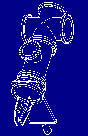
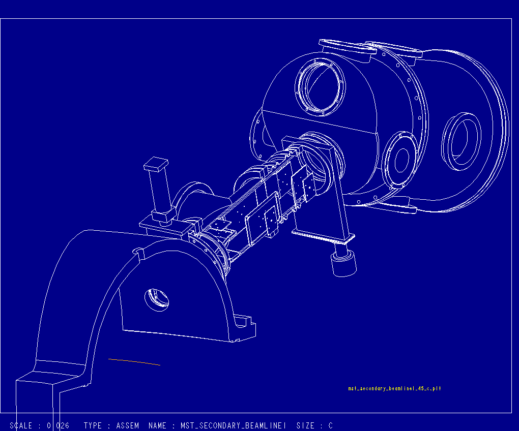
Ortho View |
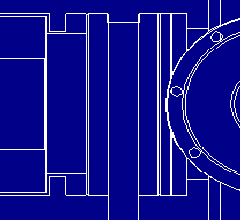
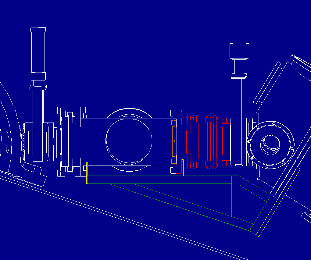
Side View |
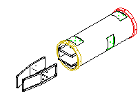
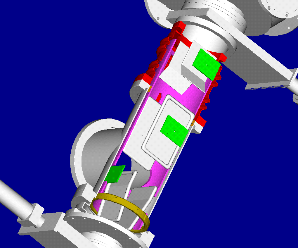
Orientation W.R.T. X-Over sweep plates |
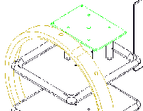
Support tube removed |

Orientation W.R.T. X-Over sweep plates |

From the ion's point of view |
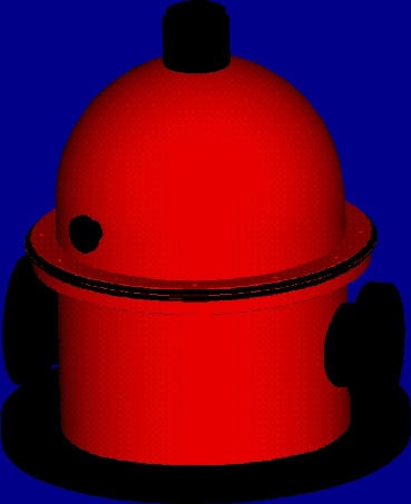
Dogs need not apply themselves here |
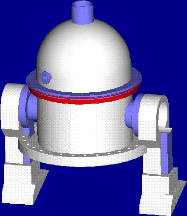
Have you seen C3PO? |
NitPickers: Don't bother pointing out the pix's imperfections, for I know them
'em better than you ever will.
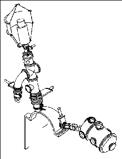
Ortho |
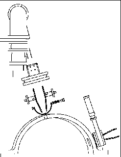
Side: Looking perpendicular to the left edge of the torus seen in "Ortho". |
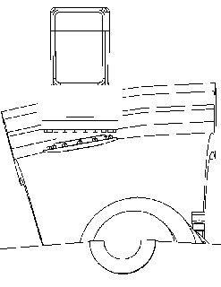
Top: Looking perpendicular to the top of the gat
e valve. |
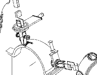
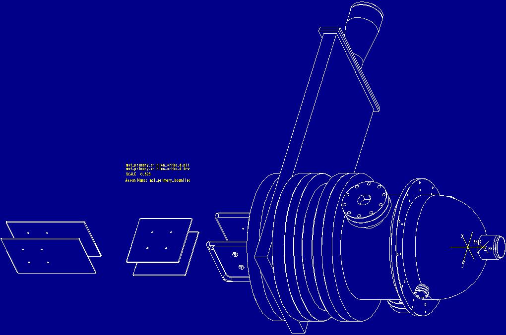
Sweep Plates Galore |
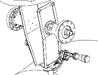
R2D2's innards: Better view of the X-Over plates and shutter |
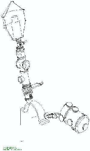
Uday: I suggest you place your pix to the right of your pos ter, Lei's to the left, for easy compairison. |
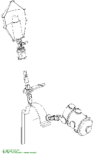
Lei: This was the best way I came up with to see your X-Ove r system |
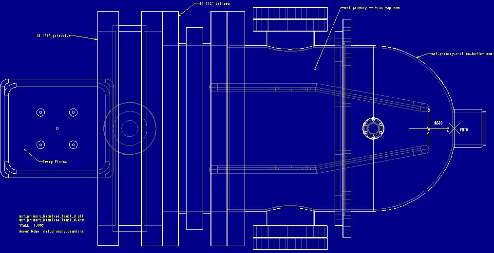
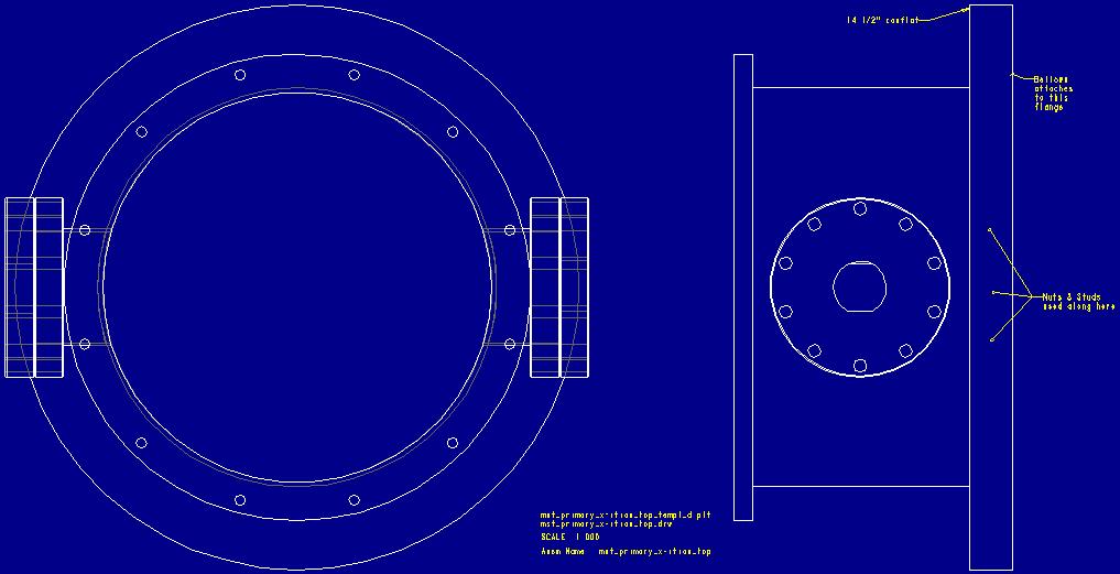
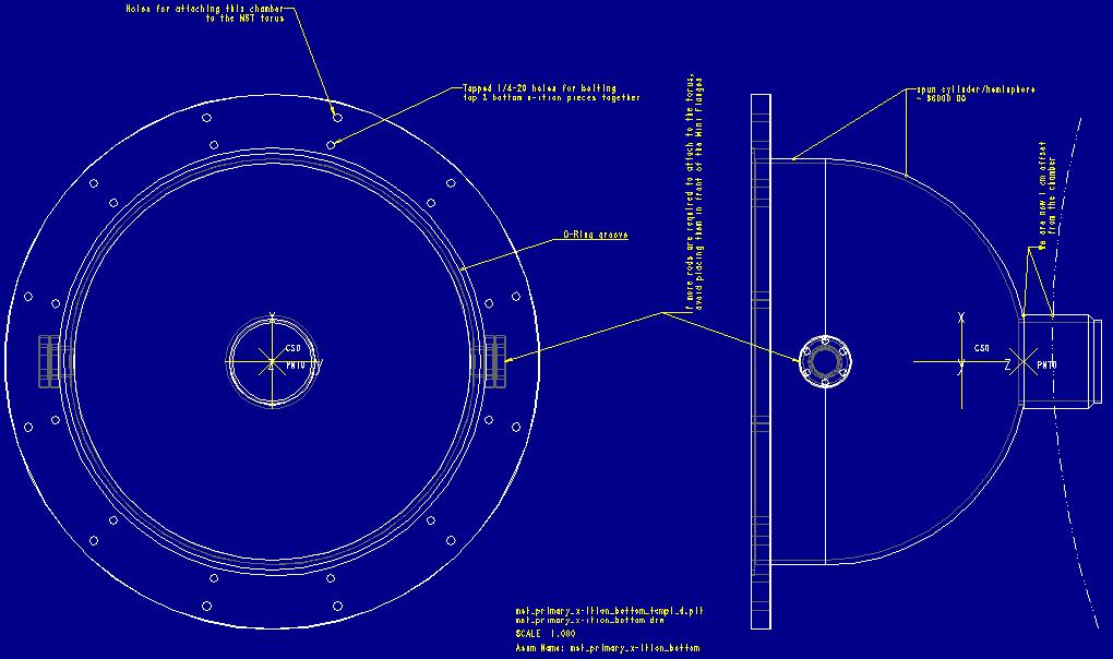
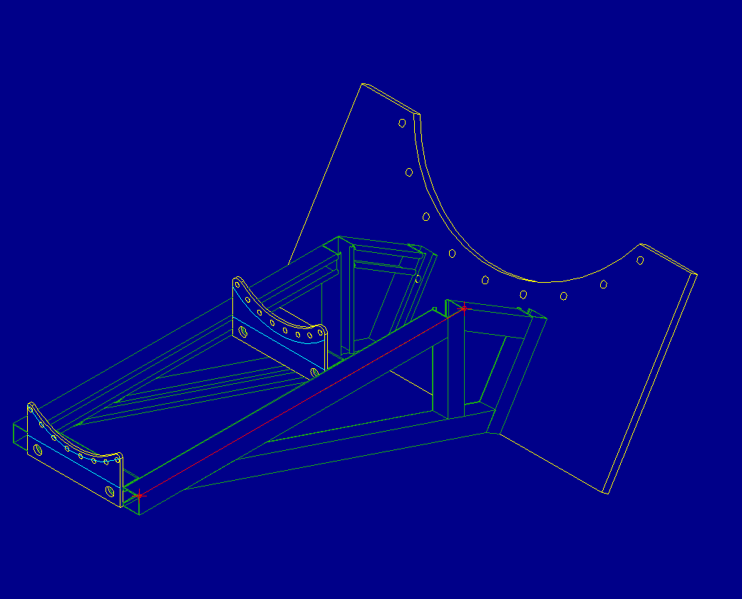
"D" size drawings for discussion. Pen velocity has been set to 4 cm/sec. Click on the image to download the HPGL file. Scales are 1:1, with the e xception of the Ortho.
This view shows the analyzer position fro m 0 to -20 degrees offset from the exit port axis. Minimum distance between th e analyzer and stair well is approximatly 5".
Typical beam profile grid. The wires are 4 mi
l. Spacing is 2, 1, and 1/2 cm.
Top Viewof the secondary system. The analyze
r is aligned to the center of the outlet port. The light blue line is the "req
uired walkway". The outer white boarders are the MST bottom floor dimensions.
This is the perpendicular-to-exit
view . The skinny white lines represent the mid-plane deck.
Siamiese Twin analyzer showing the walkw
ay/stairwell. There is ~16" betweeen the chamber(red cross) and hole in the fl
oor. Suck it in! The analyzers are =/- 5 degrees from centerline. Pivot point
(CS2) in center of bellows
Differentview
Lei's additional analyzer. 15 degrees.
You have less thn 9" between the stairwell and analyzer.......
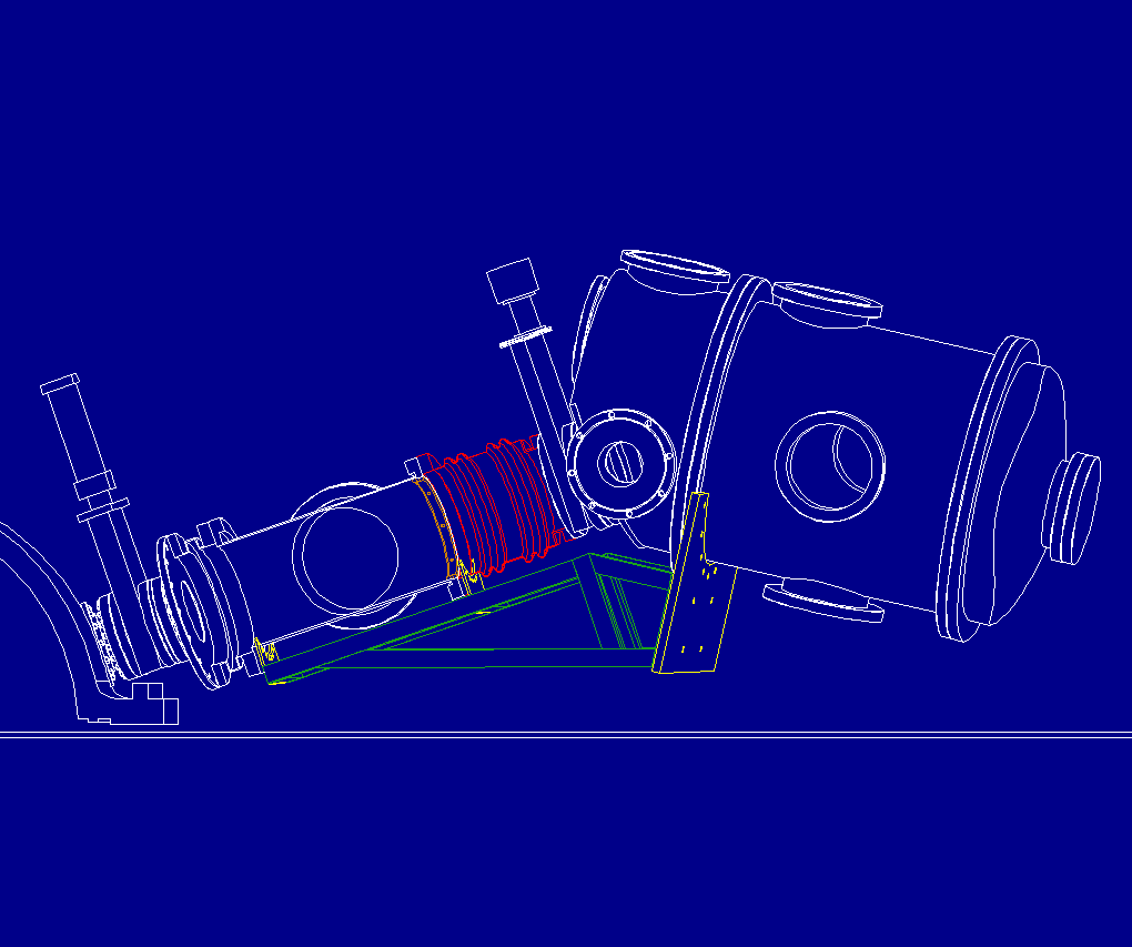
As per Uday's request of the week, the following........ Siamiese Twins Take Two This view shows the analyzer rotated +/- 5 degrees, up/down from it's neutral position. Lei , you might want to know there is a grand total of 36.4 inches between the bel lows flange to the analyzer's entrance flange...The rest of you, there is 5 1/ 8 between the deck and lowest point of the pictured analyzer.
An ortho view of the whole system. You might notice the slit adjusments have disappeared. They have. The computer ate them.
This side view is the same as Siamiese T wins Take Two, except the beamline is also shown.
Primary Beamline Notes:
The beamline now has the 3 degree lean.
Ignore the twist orientation of the beamline. It's only there to get a better
view of it's structure.
