|
In high-speed circuits, transmission line effects tend to distort signals on path that are long compared to the wavelength of the signals propagating on the path. This is rather the case in modern high speed backplain buses of digital computers. Therefore we investigate these effects.
| Parameters of Transmission Lines |
The equivalent circuit for a transmission line is shown in figure below:
|
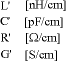
The parameters representing values for unit length are as follows:
 Parameters of a transmission line |
The charcteristic impedance of the transmission line is calculated as follows:
 Characteristic impedance of a transmission line |
Since the losses of the transmission lines in digital system buses can be neglected, the characteristic impedance becomes real and has the following value:
 Simplified charasteristic impedance |
Another important parameter of a transmission line is the propagation time between the two ends. For long buses it is more dominant than the propagation delays caused by the line drivers. The propagation delay of a transmission line is calculated as follows:
Propagation delay on a transmission line |
Finally, important calculated parameters of a transmission line are the reflection coefficients:
 Reflection coefficients of a transmission line |
where RG and RL are the generator and load resistances, respectively.
| Phenomenons on Transmission Lines |
Phenomenons on a transmission line is shown by the applet below. Adjustable parameters on it are: generator impedance ZG, characteristic impedance Z0 and load impedance ZL. In the case of the load impedance also infinite value can be input entering string inf. Finally X is for the location where the voltage is to be displayed. Its value must be between 0 and 100.
Impressing a voltage on the begin of the line it will not be present at the end of the line immediately. Instead it will propagate down to the end with a finite speed. It can be seen there only after the propagation delay.
Going into details, followings happen:
The Applet
Observe the tranzient phenomenons for some typical parameter values!
| Measuring the Line Impedance |
Since it is diffucult to measure or calculate L and C of a transmission line the characteristic impedance is usually measured. The basis of the measurement ....
Web page design by Adam Traidman