Impulse Breakdown Experiments
We are using the Febetron Pulser as a high energy source to produce
pulses for dielectric breakdown experiments, which requires voltages in
the megavolt region. The experiments are done
on a pulse basis and the pulse length is chosen to be comparable to the time
scale for the onset of breakdown, which is about 20 nano-seconds.
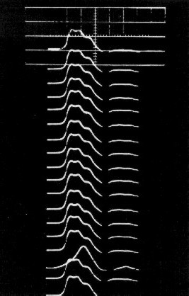
The voltage waveform pulses look like the samples below. Of the 18 pulses
in the figure, all are normal except number 16 (pulses labeled top to bottom) which is a prefire.
Polymethylmethacrylate (PMMA) dielectric specimens were used
for the impulse breakdown tests. In some cases, specimens were deliberately altered
by surface scribing, pin pricking, drilling small dimples, drilling
holes in portions of laminated specimens, and combinations of these techniques.
The apparatus used included a pulse generator (Febetron Model 2020),
an aqueous resistive load, and a
specimen fixture (shown with electrodes).
A diagram of the setup is shown below:
- a. Marx Bank column pressurized with nitrogen
- b. Freon
- c. Transformer oil
- d. Aqueous resistive load of 380 ohms
- e. Back port for high voltage vacuum photodiode
- f. Front port for lucite observation window to 4"x5" press camera
- g. Upper port for lucite observation window
- h. Rogowski coil to be connected with 1 micro-second integrator
- i. 1 micro-second integrator for current measurement
- j. Capacitance divider for specimen voltage
- k. Oil handling port
- l. Generator voltage gage
When a single pulse having an amplitude of about 2 MV strikes the specimen,
breakdown occurs. Partial and complete breakdown channels are formed. A
partial channel has a tree-like structure with many branches, each branch
having a hollow beady structure, with the beads being severval micrometers in
diameter. A complete channel is of the same nature as a partial channel except
it contains one or more branches that extend all the way though the
dielectric. Intense light emission occurs during the period of excitation
from both partial and complete channels. The luminosity suggests that highly
excited atoms in the gaseous state (i.e. gaseous plasma) is contained in the
channels. Breakdown conduction occurs by way of this gaseous plasma in the
complete channels, and it is not electronic conduction through the solid
dielectric.
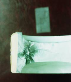
Shown below are photos taken from sample breakdown specimens:
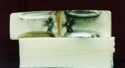
1. View from both sides of breakdown induced fracture surfaces.
2. Fusion of two trees growing toward each other from opposite electrode
sites.
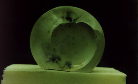
3. Large stress crack present before breakdown testing. View shown was taken
just after removing specimen. Oil is believed to have seeped between
dielectric and anode electrode prior to breakdown test.
Back to Homepage